How a Bluetooth Low Energy (BLE) pairing solution via NFC was developed using two of our reference development boards
This post entry provides a detailed description of how a Bluetooth Low Energy (BLE) pairing solution via NFC was developed using two of our reference development boards:
- The NTAG I2C plus kit for Arduino pinout.
- The Freedom KW41Z board.
NFC for easy one-tap pairing solution
NFC pairing is one popular feature you can find in cameras, speakers, printer, routers, wearables and many more. Just bringing two NFC-enabled devices close together is all it takes to create a connection. Just to mention a few of examples, with just a swipe you can:
- Connect your phone to a wireless speaker.
- Connect your new devices to the home network.
- Connect accessories to the control unit.
In all these scenarios… NFC and Bluetooth are a perfect combination, since the pairing process with NFC becomes:
- Faster compared to the traditional pairing methods.
- Easier, reducing technical support.
- More reliable, making sure you connect to the right device.
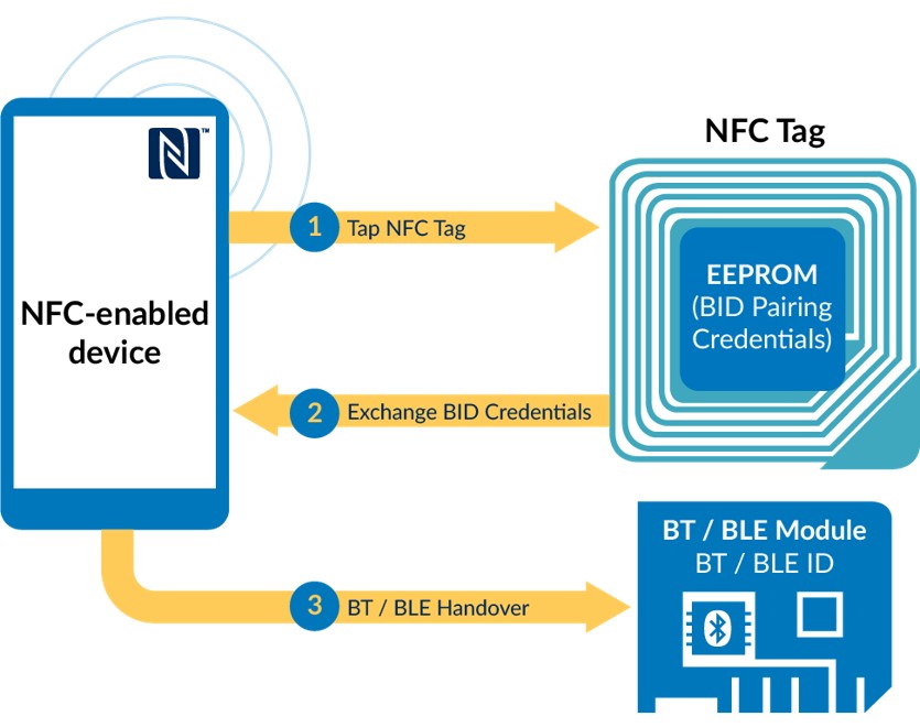
The technical basis for this “tap to connect” process is provided in the NFC Connection Handover specification running atop the NFC Forum protocol stack. It defines a framework of messages and data containers that allow bootstrapping of alternative (i.e., other than NFC) carrier connections in a standardized way. For this reason, NFC pairing solution offers a unified user experience and interoperability across different manufacturers.
NFC solutions to implement secure simple pairing
There are two types of solutions recommended to add NFC pairing functionality to designs:
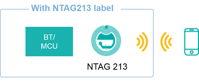
NFC static pairing with NTAG 213
The first solution is embedding an NTAG 213 NFC label. In such a case, the pairing credentials need to be previously loaded in to the tag memory as well as in the device MCU during manufacturing.
NFC dynamic pairing with NTAG I2C plus
The second solution is embedding an NTAG I2C plus tag. In such a case, the pairing credentials can be dynamically updated by the device MCU during the product lifetime. In addition, other features such as an automatic wake-up field detection signal are possible.
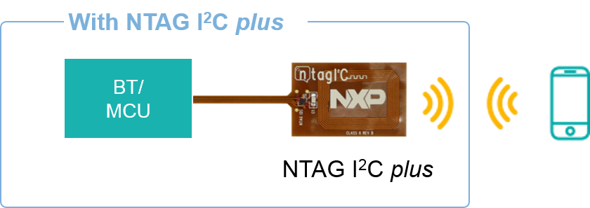
Precisely, the combination of a passive NFC interface with a contact I2C interface allows the product to behave as a tag and be read via NFC and to connect to a host or application processor via I2C. In addition, NDEF messages can be generated and updated by the host MCU depending on the application requirements. Later, these NDEF messages can be read by any NFC phone, including iOS devices with the latest OS version.

Hardware setup
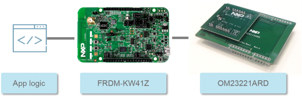
Mapping the previous diagram to the demo hardware, we have:
- The NTAG I2C plus tag, using the Arduino pinout kit
- The MCU, using Kinetis KW41Z.
- The applicatiob logic, which updates the NDEF contents based on different use cases.
Some details about the hardware used in the next sections:
Kinetis KW41Z
The Kinetis KW41Z is a high integrated chip with multi-protocol radio features enabling Bluetooth Low Energy (BLE) and 802.15.4 radio protocols such as Thread. KW41Z has as large memory of 512KB that can support multiple radio protocols running in a single application instace and implements nine low-power modes and a wide operating voltage range (0.9V/4.2V), for optimum current consumption. Finally, the software support package includes: BLE, Thread and 802.15.4 generic network stacks, several sample demo apps, support for RTOS and full integration in MCUXpresso.
The Kinetis KW41Z evaluation is supported with the FRDM-KW41Z development board. The board main components are: a reference crystal, an accelerometer, an Arduino header, some LEDs and buttons, a JTAG and OpenSDA connectors,and an external flash memory.
NTAG I2C plus kit for Arduino pinout
The NTAG I2C plus Arduino kit consist of two PCBs stacked together:
- The upper PCB is the antenna board with the connected tag
- The lower PCB is an interface adaptor board to the Arduino pinout.
This kit can be used to connect and evaluate the NTAG I2C plus into many popular MCUs with Arduino compliant headers, for example: Kinetis (e.g. KW41Z, i.MX (e.g. UDOO Neo, i.MX 6UL, i.MX 6 ULL, i.MX 7D) and LPC MCUs (e.g. LPCXpresso MAX, V2 and V3 boards).
The kit support package includes several software examples, including the BT pairing example based on KW41Z.

The OM29110ARD is a generic interface board which offers support for connection to any PCB implementing Arduino connectors. It exposes:
- 3.3V and 5V power supply pins.
- I2C , SPI and UART host interfaces.
- Generic GPIOs (e.g. to be used for field detect, interrupts, reset pins or others)
As such, it allows the NTAG I2C plus to be plugged into Arduino devices seamlessly.

Once the NTAG I2C plus board is stacked on the KW41Z, the pining routing between the two boards is as follows. It uses:
-
- The I2C interface pins.
- The 3.3V supply pin.
- One GPIO is routed for the field detection pin.
- The Vout, for the energy harvesting pin.
- The ground reference.

BLE pairing with NFC on KW41Z and NTAG I2C plus
This section details how the Bluetooth Low Energy (BLE) pairing with NFC on KW41Z and NTAG I2C plus works. The following block diagram is a simplified representation of the demo that shows:
- The Bluetooth and NFC interfaces
- The buttons and LEDs involved in the process.

Starting BLE advertising
After SW4 is pressed:
- The application goes from IDLE to searching mode, advertising the BLE device
- The LED 3 starts blinking in RED color.

Writing BLE pairing NDEF message
Once the BLE advertising is activated, the next step is for the KW41 to write the pairing message into the NTAG I2C plus memory. After SW3 is pressed:
- The KW41 uses the I2C interface with the NTAG I2C plus to load a pre-defined NDEF message with the BLE pairing details.
- At the same time, the LED 4 is set to GREEN.

Pairing with the BLE device
While the LED 4 is set to green, the BLE pairing message is exposed through the NTAG I2C plus RF interface. During this interval, any NFC-enabled device:
- Can read out the NDEF pairing message.
- Pass the BT credentials to the Android system or the host processor.
- And automatically create a Bluetooth link according to the exchanged network credentials. In case of an Android system, no third-party implementation is needed on this part as long as the pairing message follows the NFC Forum specifications.

Writing default NDEF message
Once the pairing information is read out of the NTAG I²C plus, the KW41Z removes the pairing content and turns back to normal operation mode. In addition, in this specific demo, the NDEF pairing message is programmed to remain in the NTAG I²C plus memory for only ten seconds. After these 10 seconds:
- The green LED is switched off.
- And the pairing NDEF message is overwritten by the default NDEF about the NTAG I²C plus demo app.

Video
The following video shows how the Bluetooth Low Energy (BLE) pairing with NFC on KW41Z and NTAG I2C plus works.
How to integrate NTAG I2C plus into FRDM-KW41Z hid_device sample project
In this section, we describe, step by step, how NFC is integrated in an existing default demo application taken from the KW41Z support package.
FRDM-KW41Z startup
In the board website, there are very clear instructions on how to get started www.nxp.com/demoboard/FRDM-KW41Z. For instance:
- How to test KW41Z.
- How to get the tools, in our case: MCUXpresso, and the SDK for KW41Z.
- How to import, build and runn the examples included in the SDK for KW41Z, in our case: the ones inside the wireless_examples folder

Importing FRDM-KW41Z SDK and hid_device sample project
After that, we import the FRDM-KW41Z SDK and we import the sample project used as a basis for adding NTAG I2C plus support, this is the hid_device example located under the wireless/Bluetooth folder.

Importing NTAG I2C plus middelware
The NTAG I2C plus middleware can be easily imported as a new folder in the project tree using the MCUXpresso File / Import menu. Once imported, the internal structure of the middleware should have this structure:
- HAL_I2C: The HAL_I2C files support access to the Kinetis I2C interface.
- HAL_ISR: The HAL_ISR files support the interrupt handling and callback registration for the Kinetis MCU.
- HAL_NTAG: The HAL_NTAG source files provide an API that allow you to communicate with the NTAG chip and implements the NTAG command set to perform memory access operations from the I2C interface. For instance, this API can be used to perform:
- Read / Write memory operations on EEPROM and SRAM (for example, to read data, you just need to indicate the memory address and length of the data to be read)
- Read / Write access to NTAG I2C plus registers (for example, you just need to indicate the register macro to be read).
- Functions for enabling the pass-through mode and handling the data exchange between interfaces (setting the data transfer direction is as easy as using this function).
- HAL_TMR: The HAL_TMR files support access to the timing hardware of the Kinetis MCU.

Adding / changing GPIO pin settings
All pin and GPIO settings are defined within the pin_mux.c file. For our application, the I2C pins need and a GPIO for the field detection need to be enabled.
Regarding the host interface: the I2C pins for NTAG communication are configured using the BOARD_InitI2C() function, it sets the required I2C port (port 0 for this MC) and set the right mode for the clock (SCL) and data (SDA) lines. Regarding the field detection: it is defined within the source code even though it is not used so far. It is left defined for future use.
Within the pin_mux.c file, there are other functions which initialize; for instance, the buttons, LEDs, etc. These functions are called during the hardware initialization.

NTAG I2C plus software and hardware initialization
We move to the main_application, where some pieces of code need to be added. All code that has been added, is inside the #ifdef NTAG_I2C clause. First, we added:
- The I2C_driver and the ntag_app header files .
- The ntag_handle handler declaration.
Then, the HW initialization is performed calling I2C_initDevice and the NFC_Initdevice() function is called to fill the ntag_handle software handler.

HID_device demo extensions
The BLE demo application is written in the hid_device.c file and the whole behavior is handled in this file. The C-code printout in the blue box below shows the content of the BleApp_HandleKeys() function, which handles the BLE activity and the changes made related to the NFC use case. Similarly, all new code additions are within the #ifdef NTAG_I2C clause.
Mainly, the BleApp_HandleKeys() function function was extended to:
- Copy the pairing NDEF message to the NTAG I2C plus chip when the button SW3 is pressed.
- Set the LED 3 to green while the pairing NDEF message is available.
- Start a timer counter from the moment the SW3 button is pressed
In addition, when the time counter is expired (expiration was defined to 10 seconds):
- The memory content of the NTAG I2C plus chip is overwritten by default NDEF message.
- The LED 3 is set to off.

NDEF message for BLE pairing definition
The last part missing to cover the NFC integration into the KW41Z refers to the files created within the application to declare the NDEF pairing and NDEF messages.
The NFC Data Exchange Format (NDEF) is the NFC Forum specification defining an interoperable, common data format for information stored in NFC tags and NFC devices. The spec also details how to enable tags to deliver instructions to an NFC device so that the device will perform a specific action when a particular tag is read (open a browser, initiate a phone call, pairing, etc.). Every NDEF message can be automatically processed by any NFC device and execute the appropriate action without requiring the installation of any customized software / application and independently of the hardware manufacturer.
There are several NDEF record formats that you can use in your implementation. Each NDEF record indicates to the application processor which kind of payload the message carries. In our demo app, the default NDEF message used belongs to a smart poster record and the NDEF pairing message, follows the protocol defined in the NFC Forum connection handover specification.
Going to the source code, two application files for the NDEF handling were created:
- The app_ntag.h declares the two NDEF messages used in this demo.
- The app_ntag.c, implements a function which writes the NDEF message into the tag.
As mentioned, the NDEF used for this BLE pairing was built according to the Connection Handover and BT secure simple pairing specifications and rules. On the image below, we copied the declaration of the NDEF pairing message. This is actually the hex bytes that are written into the tag memory. To highlight son relevant parts:
-
- We find the capability container and the NDEF TLV. These two fields are used by the NFC device to detect if the tag is loaded with NDEF formatted data into a Type 2 tag (like the NTAG I2C plus).
- After that, we find the record type name. This is the MIME type for the Bluetooth out of band pairing (written in its ASCII representation).
- It is followed by the device Bluetooth MAC address, and the complete local name (Freescale HID).
- The terminator TLV
In case you are interested to know more about the NDEF message structure, you can check the NFC Forum specifications

The data (MAC address 00:04:9F:00:00:04 & device name FSL_HID) read by the NFC device is sent to the Bluetooth controller to establish the Bluetooth connection.
Default NDEF message definition
The NDEF used as the default_ndef message consist of two records:
- The first record was built according to the SmartPoster specification from the NFC Forum, which describe how to store a plain message followed by an URL.
- The second record is what is called Android Application record.
On the image below, we copied the declaration of the NDEF default message. To highlight son relevant parts:
- As the NDEF BLE message, the first data fields we find correspond to the container and the NDEF TLV structure for a Type 2 Tag.
- Then, we find the smart poster record, which includes a text field. In this example, it codes the text “NTAG I2C Explorer” and a URI field which codes a the NTAG Explorer kit website URL.
- After that, we find the Android application record, which is used to automatically launch the app or, if the app is not installed, redirect the user to Google Play.
- Finally, the terminator TLV.
 After 10 seconds, the application removes the BLE pairing NDEF and replaces it by the above described NDEF message. This can be easily demonstrated by tapping the phone after these 2 seconds, and validate that the NTAG I2C plus demo is automatically opened.
Video recorded session
Available resources
-
-
-
- BLE pairing with NFC on KW41 and NTAG I2C plus source code www.nxp.com/downloads/en/snippets-boot-code-headers-monitors/SW4223.zip
- NTAG I2C plus kit for Arduino pinout www.nxp.com/demoboard/OM23221ARD
- FRDM-KW41Z board www.nxp.com/demoboard/FRDM-KW41Z
-
-
This post entry provides a detailed description of how a Bluetooth Low Energy (BLE) pairing solution via NFC was developed using two of our reference development boards:
-
-
-
- The NTAG I2C plus kit for Arduino pinout.
- The Freedom KW41Z board.
-
-
NFC for easy one-tap pairing solution
NFC pairing is one popular feature you can find in cameras, speakers, printer, routers, wearables and many more. Just bringing two NFC-enabled devices close together is all it takes to create a connection. Just to mention a few of examples, with just a swipe you can:
-
-
-
- Connect your phone to a wireless speaker.
- Connect your new devices to the home network.
- Connect accessories to the control unit.
-
-
In all these scenarios… NFC and Bluetooth are a perfect combination, since the pairing process with NFC becomes:
-
-
-
- Faster compared to the traditional pairing methods.
- Easier, reducing technical support.
- More reliable, making sure you connect to the right device.
-
-
The technical basis for this “tap to connect” process is provided in the NFC Connection Handover specification running atop the NFC Forum protocol stack. It defines a framework of messages and data containers that allow bootstrapping of alternative (i.e., other than NFC) carrier connections in a standardized way. For this reason, NFC pairing solution offers a unified user experience and interoperability across different manufacturers.
NFC solutions to implement secure simple pairing
There are two types of solutions recommended to add NFC pairing functionality to designs:
NFC static pairing with NTAG 213
The first solution is embedding an NTAG 213 NFC label. In such a case, the pairing credentials need to be previously loaded in to the tag memory as well as in the device MCU during manufacturing.
NFC dynamic pairing with NTAG I2C plus
The second solution is embedding an NTAG I2C plus tag. In such a case, the pairing credentials can be dynamically updated by the device MCU during the product lifetime. In addition, other features such as an automatic wake-up field detection signal are possible.
Precisely, the combination of a passive NFC interface with a contact I2C interface allows the product to behave as a tag and be read via NFC and to connect to a host or application processor via I2C. In addition, NDEF messages can be generated and updated by the host MCU depending on the application requirements. Later, these NDEF messages can be read by any NFC phone, including iOS devices with the latest OS version.
Hardware setup
Mapping the previous diagram to the demo hardware, we have:
-
-
-
- The NTAG I2C plus tag, using the Arduino pinout kit
- The MCU, using Kinetis KW41Z.
- The applicatiob logic, which updates the NDEF contents based on different use cases.
-
-
Some details about the hardware used in the next sections:
Kinetis KW41Z
The Kinetis KW41Z is a high integrated chip with multi-protocol radio features enabling Bluetooth Low Energy (BLE) and 802.15.4 radio protocols such as Thread. KW41Z has as large memory of 512KB that can support multiple radio protocols running in a single application instace and implements nine low-power modes and a wide operating voltage range (0.9V/4.2V), for optimum current consumption. Finally, the software support package includes: BLE, Thread and 802.15.4 generic network stacks, several sample demo apps, support for RTOS and full integration in MCUXpresso.
The Kinetis KW41Z evaluation is supported with the FRDM-KW41Z development board. The board main components are: a reference crystal, an accelerometer, an Arduino header, some LEDs and buttons, a JTAG and OpenSDA connectors,and an external flash memory.

NTAG I2C plus kit for Arduino pinout
The NTAG I2C plus Arduino kit consist of two PCBs stacked together:
-
-
-
- The upper PCB is the antenna board with the connected tag
- The lower PCB is an interface adaptor board to the Arduino pinout.
-
-
This kit can be used to connect and evaluate the NTAG I2C plus into many popular MCUs with Arduino compliant headers, for example: Kinetis (e.g. KW41Z, i.MX (e.g. UDOO Neo, i.MX 6UL, i.MX 6 ULL, i.MX 7D) and LPC MCUs (e.g. LPCXpresso MAX, V2 and V3 boards).
The kit support package includes several software examples, including the BT pairing example based on KW41Z.
The OM29110ARD is a generic interface board which offers support for connection to any PCB implementing Arduino connectors. It exposes:
-
-
-
- 3.3V and 5V power supply pins.
- I2C , SPI and UART host interfaces.
- Generic GPIOs (e.g. to be used for field detect, interrupts, reset pins or others)
-
-
As such, it allows the NTAG I2C plus to be plugged into Arduino devices seamlessly.
Once the NTAG I2C plus board is stacked on the KW41Z, the pining routing between the two boards is as follows. It uses:
-
-
-
-
- The I2C interface pins.
- The 3.3V supply pin.
- One GPIO is routed for the field detection pin.
-
-
- The Vout, for the energy harvesting pin.
- The ground reference.
-
-
BLE pairing with NFC on KW41Z and NTAG I2C plus
This section details how the Bluetooth Low Energy (BLE) pairing with NFC on KW41Z and NTAG I2C plus works. The following block diagram is a simplified representation of the demo that shows:
-
-
-
- The Bluetooth and NFC interfaces
- The buttons and LEDs involved in the process.
-
-
Starting BLE advertising
After SW4 is pressed:
-
-
-
- The application goes from IDLE to searching mode, advertising the BLE device
- The LED 3 starts blinking in RED color.
-
-
Writing BLE pairing NDEF message
Once the BLE advertising is activated, the next step is for the KW41 to write the pairing message into the NTAG I2C plus memory. After SW3 is pressed:
-
-
-
- The KW41 uses the I2C interface with the NTAG I2C plus to load a pre-defined NDEF message with the BLE pairing details.
- At the same time, the LED 4 is set to GREEN.
-
-
Pairing with the BLE device
While the LED 4 is set to green, the BLE pairing message is exposed through the NTAG I2C plus RF interface. During this interval, any NFC-enabled device:
-
-
-
- Can read out the NDEF pairing message.
- Pass the BT credentials to the Android system or the host processor.
- And automatically create a Bluetooth link according to the exchanged network credentials. In case of an Android system, no third-party implementation is needed on this part as long as the pairing message follows the NFC Forum specifications.
-
-
Writing default NDEF message
Once the pairing information is read out of the NTAG I²C plus, the KW41Z removes the pairing content and turns back to normal operation mode. In addition, in this specific demo, the NDEF pairing message is programmed to remain in the NTAG I²C plus memory for only ten seconds. After these 10 seconds:
-
-
-
- The green LED is switched off.
- And the pairing NDEF message is overwritten by the default NDEF about the NTAG I²C plus demo app.
-
-
Video
The following video shows how the Bluetooth Low Energy (BLE) pairing with NFC on KW41Z and NTAG I2C plus works.
How to integrate NTAG I2C plus into FRDM-KW41Z hid_device sample project
In this section, we describe, step by step, how NFC is integrated in an existing default demo application taken from the KW41Z support package.
FRDM-KW41Z startup
In the board website, there are very clear instructions on how to get started www.nxp.com/demoboard/FRDM-KW41Z. For instance:
-
-
-
- How to test KW41Z.
- How to get the tools, in our case: MCUXpresso, and the SDK for KW41Z.
- How to import, build and runn the examples included in the SDK for KW41Z, in our case: the ones inside the wireless_examples folder
-
-
Importing FRDM-KW41Z SDK and hid_device sample project
After that, we import the FRDM-KW41Z SDK and we import the sample project used as a basis for adding NTAG I2C plus support, this is the hid_device example located under the wireless/Bluetooth folder.
Importing NTAG I2C plus middelware
The NTAG I2C plus middleware can be easily imported as a new folder in the project tree using the MCUXpresso File / Import menu. Once imported, the internal structure of the middleware should have this structure:
-
-
-
- HAL_I2C: The HAL_I2C files support access to the Kinetis I2C interface.
- HAL_ISR: The HAL_ISR files support the interrupt handling and callback registration for the Kinetis MCU.
- HAL_NTAG: The HAL_NTAG source files provide an API that allow you to communicate with the NTAG chip and implements the NTAG command set to perform memory access operations from the I2C interface. For instance, this API can be used to perform:
- Read / Write memory operations on EEPROM and SRAM (for example, to read data, you just need to indicate the memory address and length of the data to be read)
- Read / Write access to NTAG I2C plus registers (for example, you just need to indicate the register macro to be read).
- Functions for enabling the pass-through mode and handling the data exchange between interfaces (setting the data transfer direction is as easy as using this function).
- HAL_TMR: The HAL_TMR files support access to the timing hardware of the Kinetis MCU.
-
-
Adding / changing GPIO pin settings
All pin and GPIO settings are defined within the pin_mux.c file. For our application, the I2C pins need and a GPIO for the field detection need to be enabled.
Regarding the host interface: the I2C pins for NTAG communication are configured using the BOARD_InitI2C() function, it sets the required I2C port (port 0 for this MC) and set the right mode for the clock (SCL) and data (SDA) lines. Regarding the field detection: it is defined within the source code even though it is not used so far. It is left defined for future use.
Within the pin_mux.c file, there are other functions which initialize; for instance, the buttons, LEDs, etc. These functions are called during the hardware initialization.
NTAG I2C plus software and hardware initialization
We move to the main_application, where some pieces of code need to be added. All code that has been added, is inside the #ifdef NTAG_I2C clause. First, we added:
-
-
-
- The I2C_driver and the ntag_app header files .
- The ntag_handle handler declaration.
-
-
Then, the HW initialization is performed calling I2C_initDevice and the NFC_Initdevice() function is called to fill the ntag_handle software handler.
HID_device demo extensions
The BLE demo application is written in the hid_device.c file and the whole behavior is handled in this file. The C-code printout in the blue box below shows the content of the BleApp_HandleKeys() function, which handles the BLE activity and the changes made related to the NFC use case. Similarly, all new code additions are within the #ifdef NTAG_I2C clause.
Mainly, the BleApp_HandleKeys() function function was extended to:
-
-
-
- Copy the pairing NDEF message to the NTAG I2C plus chip when the button SW3 is pressed.
- Set the LED 3 to green while the pairing NDEF message is available.
- Start a timer counter from the moment the SW3 button is pressed
-
-
In addition, when the time counter is expired (expiration was defined to 10 seconds):
-
-
-
- The memory content of the NTAG I2C plus chip is overwritten by default NDEF message.
- The LED 3 is set to off.
-
-
NDEF message for BLE pairing definition
The last part missing to cover the NFC integration into the KW41Z refers to the files created within the application to declare the NDEF pairing and NDEF messages.
The NFC Data Exchange Format (NDEF) is the NFC Forum specification defining an interoperable, common data format for information stored in NFC tags and NFC devices. The spec also details how to enable tags to deliver instructions to an NFC device so that the device will perform a specific action when a particular tag is read (open a browser, initiate a phone call, pairing, etc.). Every NDEF message can be automatically processed by any NFC device and execute the appropriate action without requiring the installation of any customized software / application and independently of the hardware manufacturer.
There are several NDEF record formats that you can use in your implementation. Each NDEF record indicates to the application processor which kind of payload the message carries. In our demo app, the default NDEF message used belongs to a smart poster record and the NDEF pairing message, follows the protocol defined in the NFC Forum connection handover specification.
Going to the source code, two application files for the NDEF handling were created:
-
-
-
- The app_ntag.h declares the two NDEF messages used in this demo.
- The app_ntag.c, implements a function which writes the NDEF message into the tag.
-
-
As mentioned, the NDEF used for this BLE pairing was built according to the Connection Handover and BT secure simple pairing specifications and rules. On the image below, we copied the declaration of the NDEF pairing message. This is actually the hex bytes that are written into the tag memory. To highlight son relevant parts:
-
-
-
- We find the capability container and the NDEF TLV. These two fields are used by the NFC device to detect if the tag is loaded with NDEF formatted data into a Type 2 tag (like the NTAG I2C plus).
- After that, we find the record type name. This is the MIME type for the Bluetooth out of band pairing (written in its ASCII representation).
- It is followed by the device Bluetooth MAC address, and the complete local name (Freescale HID).
- The terminator TLV
-
-
In case you are interested to know more about the NDEF message structure, you can check the NFC Forum specifications
The data (MAC address 00:04:9F:00:00:04 & device name FSL_HID) read by the NFC device is sent to the Bluetooth controller to establish the Bluetooth connection.
Default NDEF message definition
The NDEF used as the default_ndef message consist of two records:
-
-
-
- The first record was built according to the SmartPoster specification from the NFC Forum, which describe how to store a plain message followed by an URL.
- The second record is what is called Android Application record.
-
-
On the image below, we copied the declaration of the NDEF default message. To highlight son relevant parts:
-
-
-
- As the NDEF BLE message, the first data fields we find correspond to the container and the NDEF TLV structure for a Type 2 Tag.
- Then, we find the smart poster record, which includes a text field. In this example, it codes the text “NTAG I2C Explorer” and a URI field which codes a the NTAG Explorer kit website URL.
- After that, we find the Android application record, which is used to automatically launch the app or, if the app is not installed, redirect the user to Google Play.
-
- Finally, the terminator TLV.
-
-

After 10 seconds, the application removes the BLE pairing NDEF and replaces it by the above described NDEF message. This can be easily demonstrated by tapping the phone after these 2 seconds, and validate that the NTAG I2C plus demo is automatically opened.
Video recorded session
Available resources
-
-
-
- BLE pairing with NFC on KW41 and NTAG I2C plus source code www.nxp.com/downloads/en/snippets-boot-code-headers-monitors/SW4223.zip
- NTAG I2C plus kit for Arduino pinout www.nxp.com/demoboard/OM23221ARD
- FRDM-KW41Z board www.nxp.com/demoboard/FRDM-KW41Z
-
-
Related topics

The world of payment is going cashless and money transfer is becoming digital.